White Paper: Solid-State Light Engines for Bioanalytical Instruments and Biomedical Devices
Light Intensity
Optimal signal to noise ratios are characterized quite differently for the vast array of life science applications. For example, fluorescent imaging of live cells generally requires maximum light flux and minimum exposure times timed precisely to the camera’s exposure setting. This maximizes the signal while reducing cell toxicity and photo bleaching of the fluorescent tags. Only the light flux that reaches the illuminated sample area captured by the CCD camera is of value. For fluorescing organic molecules, the angular distribution of the illumination is not critical since the absorption process is independent of incident angle. Therefore, in this case, the optimal illumination system will maximize flux over the imaged area or intensity (W/cm2).
Another example is lighting for endoscopy. The surgical or examination field inside the body is quite varied in structure and size. The CCD camera is imaging reflected light and/or fluorescence. The maximum signal is proportional to the reflected or fluorescent light flux emanating from the area imaged by the camera. Compared to fluorescence, light scattering from tissue can be highly angle dependent. However, given the random structure of the tissue, it is a reasonable approximation for most endoscopic applications that the maximum signal will be obtained by maximizing the illumination intensity. As these two examples demonstrate, intensity is most often the key parameter to maximize in solid-state illumination systems in the life sciences.
Etendue
While optimizing intensity seems straightforward, delivering optimal intensity requires an understanding of a key optical invariant, étendue1, in conjunction with the illumination delivery system. Most simply, étendue determines the maximum light flux through an optical system.
The term étendue comes from the French word for extent or spread. Etendue characterizes the spread of the light in area and angle. From the perspective of a chemist, it is the entropy of the ray bundle. To a physicist, it is the area of the source times the solid angle. Within any microscope or bioanalytical instrument, the étendue is the area of the entrance pupil times the solid angle of the light source subtended as seen by the entrance pupil. Like entropy in a chemical system, étendue can only increase in any optical subsystem. In a perfect optical system, the image produced possesses the same étendue as the source. More typically there are other constraints limiting this ideal circumstance and so optimization requires matching these étendues as best as physically possible. Etendue can be calculated for each system from the equation below:
E = A ×Ω
where A is the area of the source and Ω is the solid angle of the illumination pattern and typically is expressed in units of mm2•sr. For a non-uniform illumination source in an arbitrary medium, étendue can be expressed as:
E = n2 × A × ∫ I (θ,Φ) ∂Ω
where I is the angular intensity distribution and n is the refractive index. Most sources such as an LED, the intensity can be accurately described by a Lambertian emitter where I (θ,Φ) = Io cos (θ)
where Io is the intensity at zero degrees. For Lambertian sources, étendue can then be expressed as
E = n2 × A × π × Io × ( 1 - cos2 (θm))
where θm is the maximum collection angle of the illumination system. It is typically more convenient to rewrite this equation in terms of numerical aperture (NA):
E = A × π × Io × NA2
It is instructive to calculate étendue for a variety of light source systems, delivery systems and instruments. Table 1 provides various examples using Io equal to 1 with all systems in air and assuming all Lambertian light distributions. The data is divided into three categories: delivery light guides, solid state sources and microscope objectives.
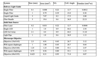
The table shows a wide range of étendue for fairly typical illumination systems employed across the life sciences. It is the match between optical source and sink that is critical to providing the maximum intensity for the range of life science tools.
The amount of light reaching the illuminated area is determined simply by the ratio of the source étendue to the instrument étendue. For example, a liquid light guide source with an étendue of 2 used in microscope with an objective étendue of 3 will deliver all of its flux to the sample. If the objective is a 40x/0.95, then only 44% of the light will reach the sample.
Maximizing intensity of the sample region necessitates taking into account the étendue of the illumination source and sink. Understanding the intensity profile of the source can lead to further optimization of the flux transfer to the sample. Exemplary cases for small, medium and large étendue conditions are considered in more detail below.
OPTICAL DESIGN considerations in bioanalysis tools
A case of small étendue
Small étendue systems demand optical subsystem designs based on the smallest of illumination sources. Practical examples include microanalysis chips with individual flow channels on the order of 100 μm diameter or ophthalmological applications in which a point source on the order of 5 - 10μm diameter is projected onto the retina of an eye. Capillary electrophoresis and cell sorters typically employ capillaries with 50μm diameter bores. Acceptance angle is limited to 15 degrees or less leading to an étendue of 4 x 10⁻⁴ mm2•sr. As a consequence of these étendue and intensity requirements, lasers are used to deliver 10 to 20mW.
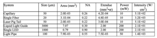
It is useful to compare the performance of various light sources used in an idealized capillary system. For each source, a typical power level is provided for 25 nm bandwidth spectral outputs. Table 2 shows effective étendue and required intensity given cases for different capillary parameters. To calculate the intensity delivered by each source type, the source output is multiplied by the ratio of the capillary étendue to the source étendue for those sources with étendue larger than that of the capillary. This étendue ratio determines the theoretical maximum light flux that can be transmitted to the target. For the laser pig tail, the étendue is smaller than the capillaries and so there is no loss in transmitted power. In a real system, there are numerous other losses that reduce the incident intensity (W/cm2). As an example, typical optical transmission systems increase the étendue of the source further reducing the delivered intensity.
Clearly, the laser is the superior performer in terms of intensity in these small étendue applications. The arc lamp pumped liquid light guide and LED deliver an order of magnitude less intensity.
Interestingly, luminescent light pipes can be designed to deliver the required intensity. This characteristic is achieved due to their intrinsically narrow size. Sufficient power is obtained by integrating the luminescence from a sufficiently long pipe. Light pipes generating sufficient intensity enable low cost, stable outputs and are a mode free alternative to lasers.
Indeed, lasers have provided for some of the most demanding microscope and instrumentation lighting requirements in bioanalysis. Where intensities on the order of 10s and 100s of W/cm2 are required, spectral narrowness no greater than a few nanometers, collimation is needed, only lasers have fit the specification. In cases where only some of these requirements are strict and others more lenient, an opportunity to provide light from an alternative source exists.
Such is the case for systems and optics designed for diagnostics in ophthalmology. Here opportunities to combine confocal scanning and optical coherence tomography exist. Moreover mechanical, electrical, optical interfaces require a high degree of integration such that the tools provide bright, coaxially aligned, multi-band outputs in a beam diameter tight enough to interrogate the human eye. Spectral and power specifications are demanding but not necessarily as high performance as has come to be expected from lasers. Luminescence light pipes seem a likely solution.
A case of moderate étendue
A less severe geometric constraint but significantly demanding optical requirement is presented by fixed and live cell imaging applications. The breadth of analytical systems span fluorescence microscopes, tools for high content screening, gene expression analysis based on a scanning microscope platform and the like. As seen in Table 1, the relevant étendues depend not only on the objective, but also on the illuminated area. This is generally determined by the microscope’s field diaphragm.
The traditional source and delivery most commonly employed in these imaging applications is an arc lamp coupled to a liquid light guide. While the guides can have larger NAs than shown in the table above, using the available NA and therefore étendue does not increase intensity at the sample. It is the ratio of the objective to the source étendue that will determine the delivered intensity.
In addition, the guide will increase the angular spread of the light and therefore increase the étendue. The collection optics for the guide will reduce intensity further as they are not optimally matched for every microscope. Each microscope’s optical train is unique requiring varying input beam diameters with either slightly converging or slightly diverging collimated light.
Compounding this issue is the inherent instability of the microscope arc lamp. The filament has considerable structure and wanders with age. Initial intensity for “virgin” bulbs can differ by as much as 100%. Intensity declines precipitously with age and failure can often be catastrophic. Transferring stable intensity from the arc lamp to the sample slide is a highly complex design problem.
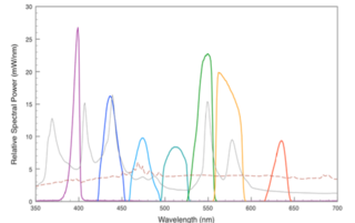
Figure 2. Light pipe outputs versus typical metal halide and xenon lamp performance. Rust colored trace represents typical xenon arc lamp (75W) output, grey trace represents typical metal halide (120W) output, colored bands represent discrete outputs generated by Lumencor Light Engine across visible spectrum.
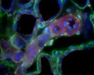
Figure 3. Four color image of tubulin (red), f-actin (white), laminin (green), Dapi (blue) generated on an Olympus IX 81 Microscope with a solid state Light Engine.
A sustainable solid-state solution based on LEDs and light pipes has been developed that is now outperforming the microscope arc lamp across the visible spectrum in terms of intensity delivered to the sample. By paying careful attention to component architecture, the étendue of sources can be well matched to the illuminated area of the microscope objective to deliver maximum intensity. The spectral output of this hybrid Light Engine solution is shown in Figure 2. 3 The representative spectra were calculated based upon measurements made using a liquid light guide with a diameter of 3 mm and a NA of 0.3. The spectra show the output from a variety of LEDs and luminescence light pipes vs. the typical performance from a metal halide lamp and xenon lamp used in microscopy.
All Light Engine sources are steered down the same optical path. They are directed in a slightly diverging co-axial beam to fill the exit pupil of the microscope objective. No losses due to external color filters or external shutters are suffered as all the switching and intensity is electronically controlled. Today such lighting is being employed to generate live and fixed cell multicolor images (figure 3) 4, for high content screening applications, in tools for digital histology and gene expression analysis and to produce video images of subcellular function.
A case of large étendue
In the least geometrically constrained examples, a fiber bundle for endoscopes or a microtiter plate or even projected illumination onto an analysis chip, provides the opportunity to utilize a relatively large source. In these cases, étendue is considered relatively large. Arc lamps have generally performed adequately in terms of power. As an example, endoscope applications are served primarily by 300 W xenon lamps. These lamps deliver up to 10W of white light when first turned on. While inexpensive sources, significant maintenance issues and safety concerns are common with these lamps.
Moreover, such broadband sources are not ideal for the growing range of needs in this imaging application. Here powerful white light for visible illumination and high definition imaging is needed. Control of the color spectrum of that light in order to produce high contrast images, well matched to the color cameras employed is a growing area of development. The trend to narrowband illumination (NBI), light for ICG excitation, endogenous fluorescence, and other imaging agents means NIR lasers are desirous. Moreover it is with the simultaneous illumination of white light and targeted fluorescence excitation, that advanced imaging will provide optical selectively to the surgical field and specificity sufficient for clinical diagnostics. Spectral and power stability and illumination uniformity are needed for safety and efficacy of treatment.
As discussed above, solid-state illumination systems can be engineered to outperform in microscope applications. The same is true for endoscopes. By scaling the étendue from microscope architecture, the hybrid solution can be designed to transfer sufficient flux to outperform the arc lamp. Figure 4 below shows the spectral output of one possible solid state solution overlaid with the output from a xenon lamp. The lamp is half way through its useful life. This data was calculated for an endoscope bore size of 4.8 mm.
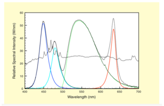
Figure 4. Endoscope Light Engine output in four colors: red, green, cyan and blue. Colored bands repre- sent band specific contributions to the white light generated from a Light Engine. The grey trace is a representative output from a 300W xenon lamp.
The trend towards smaller bore diameters with inherently smaller étendues represents a severe constraint for arc lamps. Since the delivered light flux is proportional to the étendue, there is no clear path to providing the same flux using smaller bore diameters. An example is provided in Table 3, clearly showing the illumination challenge. Estimates are also provided for a solid state solution. Here significantly more power should be possible due the ability to take advantage of sources with significantly smaller étendue and therefore optimally transfer source flux to the endoscope fiber bundle.
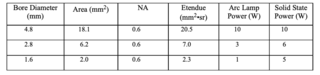
Table 3. Intensity and étendue analysis for various size conduits used with an arc lamp or a solid state source.
In addition, the hybrid lighting source is uniquely well suited for the particular case of the new endoscopes used to perform minimally invasive imaging. Powerful white light of practically any color temperature (red/green/ blue, RGB) can be generated in a way that balances spectral contributions to maximize signal/noise and contrast. In parallel, narrowband excitation for targeting specific fluorescence is addressable. Light Engines provide comprehensive spectral, temporal and spatial control of light for surgical and non-surgical procedures. Products are powerful enough to yield high contrast, real-time imaging as well as to maximize fluorescence signals. Stable, robust lighting enables long term monitoring and quantitation.
Conclusion
The design of lighting subsystems for bioanalysis is being pushed to more and more demanding performance specifications including spectral purity, spectral breadth, high power, facile switching, durability, ease of use, compact size, and reduced cost. While traditional sources have historically supported these applications with microscope lamps, lasers and LEDs, the growing realm of state of the art techniques for bioanalysis is ripe for updated lighting subsystems. Included in this growing range of applications are tools for digital pathology, high content screening, live cell imaging and endoscopy. A hybrid of solid-state lighting technologies should provide best for the demanding spatial, spectral, intensity and temporal needs of these applications. Particularly compelling is the promise of light pipes in this growing array of illumination tools.
- Jul 30, 2010
- Greivenkamp, J. E., [Field Guide to Geometrical Optics], SPIE, Field Guides vol. FG01 (2004)(opens in new window)
- S. Watkins, Director Center for Biologic Imaging, University of Pittsburgh Medical School, interview, Nov. 12, 2008(opens in new window)
- Sorensen, H. S., Andersen, P. E., Laren, N. B., Hansen, P. R., and Bornhop, D. J., " Monitoring biochemical interac- tions can serve as the basis for many diagnostic techniques," Proc. SPIE DOI: 10.1117/2.1200905.1673, (2009)(opens in new window)